Design Team Members: John Bellingham, Darren Hemingway
Supervisors: Professor G. Heppler , Professor J. McPhee
Background
In August 2000, the next generation of CanadArm will be launched into space to help assemble the International Space Station. This arm is one of the most advanced robots ever built, but because it must be light, slender, and have a long reach, its flexibility places severe restrictions on its capabilities. Crucial tasks for space station operations like capturing free flying vehicles are difficult and not guaranteed to succeed. Improving the control of this manipulator despite its inherent flexibility would be very valuable.
In addition to the benefits to space robotics, important terrestrial applications of flexible manipulator control exist. Most standard textbooks on robotics begin with the assumption that the links of the robot are rigid. This assumption is valid for robots that operate at lower speeds, or have very strong links. However, this assumption will have to be discarded in order to control faster, lighter and more accurate robots. The mechanical compliance of robots is currently cited as one of the main factors limiting robot performance.
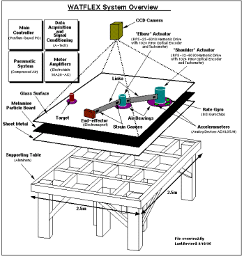
The WATFLEX facility has been established at the University of Waterloo to investigate these factors in robot manipulator control.

Overview of the WATFLEX Facility, from The Design and Integration of a Test Facility for Flexible Robotic Manipulators, D. Lovekin, G.R. Heppler, J. McPhee
Project description
The WATFLEX facility is a two degree of freedom robot whose motors are mounted on air bearings. Functioning like an air hockey table, these air bearings float the manipulator off the surface it of the table. By reducing friction through the air bearings, and moving only in the horizontal plane, WATFLEX simulates manipulator dynamics in the weightlessness of space.
The primary objectives for this project are to construct a set of flexible links for the WATFLEX facility, and implement a control strategy for operation of the flexible links. As secondary objectives, the project will include improvements to the air bearings supporting the joints, and installing the hardware for the camera system used to track the position of the robot and its target.
The construction of the flexible links includes making mounting brackets that allow for adjustment of the beam's position and orientation to account for manufacturing imprecision, dimensioning the actual links to provide the correct amount of flexibility, and installation of strain gauges on the beam. The information provided by the strain gauges will allow calculation of the manipulator's end point position and orientation.
The control algorithm will be implemented on a PC collecting information from sensors and driving the shoulder and elbow motors of the manipulator. The air bearings will be improved to increase the floating height of the manipulator, and an adjustable support system will be constructed so that a digital camera can be positioned above the manipulator. This camera will be used to acquired data on the position of the manipulator and of a target moving through the workspace. Development of an end effector to capture this target will be left to future groups.
Design methodology
The design methodology used for the development of the flexible link and mounting system was straightforward. Constraints and criteria were established, several conceptual designs were developed and one was chosen and developed in detail. The constraints and criteria are listed in the following table:
Constraints
Must
mount
to
existing
components
Must
be
adjustable
to
account
for
manufacturing
defects
Must
limit
the
coupling
between
modes
of
flexibility
Must
work
with
tolerances
on
air
bearing
performance*
*Current
air
bearing
performance
and
improved
performance
expected
after
improvements
to
air
bearing
system.
Criteria
Tip
deflection
during
standard
manoeuvre
of
10%
of
beam
length
Easily
adjustable
Simple
to
manufacture
Modular
so
that
beam
stiffness
can
be
changed
Several complex designs, including hinges and ball joints were considered for the connection between the beam and the mounting face, to allow for continuous adjustment in relation to the air bearing performance. It was decided that this type of adjustment added too much complexity and would not be necessary. If the link was built and hinges or other continuous adjustments were required, they could be added later as a modular block inserted between the flexible link and the mounting face.
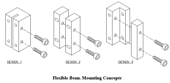
Simulation performed by Pengfei Shi gave estimates for the size of steel beam that would give the desired deflection. The closest standard size of material was chosen for the flexible beam section of the link. The design problem was thus reduced to designing the interface between the beam and the mounting face on the motor. This interface must allow for adjustment of the link in vertical translation, rotation about the longitudinal axis, and rotation about the horizontal transverse axis.
With these restrictions, the concepts shown below were developed. The third design was chosen because it was simple to manufacture, and allowed for the easiest adjustment. A detailed design was developed. Aluminium was chosen for the construction of the mounting block because of its strength, light weight and ease of machining.

Once this design was constructed, it was tested with the existing control system, and existing air bearing support. The link performed very well, providing the flexibility of easily allowing adjustments of the alignment of the beam due to changes in air bearing support. No coupling between the modes of bending were noticed. The tip deflection during a standard manoeuvre has not been measured, but appears to be approximately correct from initial tests. The design allows for easy exchange of beam components, which allows for changing the stiffness of the link easily.