The current focus of research includes:
5-Axis Tool Positioning: 5-axis Computer Numeric Controlled (CNC) machines are agile and can freely position and orient the tool axis. This agility can be used to position the cutting surfaces of the tool in close proximity to the desired surface.
Virtual Machinist: Computer Numerically Controlled (CNC) Machines follow a part program to move the tool as per the directions of the programmer. The end result is the machined part. This is inessence an open loop system. The machine only follows commands, the final result depends on the machinist. This makes the machinist a part of the system. Thus whenever a part is to be machined the machist has to be close to the machine. Virtual Machinist is a concept that knits the movement of th e machine with a simulator. As the machine moves, so does the simulted machine etc. In addition, the simulator also trackes the movement of the tool relative to the raw stock, the forces experienced by the tool, the onset of chatter, the tool life etc. In this research it is proposed that these elemtent and some others are woven into a virtual machinist, a software observer, that can be the first step to autonomous machining. Given a part, a raw stock and a library of tools the virtual machinist should be able to machine the desired part.
The research below describes various machining methods developed, to find the tool position and orientation from the geometry of the tool and the surface, over the past three decades. The methods are summarised below:
-
Principal Axis Method: In this method, the shape of the surface at the point of contact, is measured by the maximum principal curvature, and is matched to the minimum curvature at a point on the rotating tool (modelled in general as a torus). The principal curvatures of the tensor product surfaces and that of the tool (torus) form a orthogonal coordinate frames on the respective surfaces. The alignment of the two frames results in the location and orientation of the tool relative to the surface. Numerous such tool positions are found on the surface and as the CNC machine moves the tool from one of these locations to the next, the desired surface is machined into the stock.
-
Multi-Point Machining: This method emulates a coin placed in a die. The coin is cylindrical with rounded edges, a torus in other words. It sits in the die touching it in two or more points. Replacing the coin with a tool gives one tool position and orientation. Sliding the coin along a predefined path (tool path footprint) results in numerous tool position and orientations. Visting these the tool can cut the desired surface. Since the two contact points are spaced apart, the ribbon in-between and around these points meets surface finish criteria. Thus, the side step in this case can be wider than the ribbon, usually a few millimeters in comparison to a 3-axis tool poistion in which the sidestep is a fraction of a millimeter. The increased side-step results in reduced machining time.
The initial attempt at Multi-Point machining was due to Warkentin, in which the tool orientation and position were optimized to reduce the gap between surface and tool at two points. The method was computationally expensive, but proved multi-point machining. To simplify the computations, the first attempt was to simplify the tool and the positioning strategy. The Rolling Ball Method and the Arc-intersect method belong to this category.
-
Rolling Ball Method: A sphere centered at any point on the tool axis encloses the toroidal cutting surface of the tool. As the center of the tool is moved away, along the tool axis the size of the sphere, the size of the sphere grows. This concept is utilized to generrate atool position at a given point. In the method the tool axis is assumed ot align with the surface normal at the point of contact. A growing sphere is drawn with its center along the surface normal (tool axis) and a point on the surface. The interference of this sphere against the surface, in the vicinity of the contact point, is checked. When the sphere touches the surface at a second point, it is selected and the tool is positioned inside it. Since the sphere does not interfere with the surface, the tool, emclosed inside, also does does not interfere. The tool is positioned at numerous points along the surface and its orientation is determined usign the method described. As a CNC machine moves the tool along these points it machines the desired surface. The method is fast and easy to implement.
-
Arc-Intersect Method: The Arc Intersect method is an improvement over the rolling ball method. In the rolling ball method at any tool position the tool positively contact the surface at one point, however, it seldom touches the surface at the second point. The concept of Multi-point implies that it is possible to rotate the tool further and bring it closer to the desired surface, with a more optimal tool position. Arc-Intersect method finds a more optimal tool position to the rolling ball method.
-
Drop Tilt Method for Triangulated Surfaces: In the rolling ball and the arc-intersect methods the tool is approximated to find a multi-point tool position. In Drop Tilt Method (DTM) the surface is approximated as a set of triangles that touch each other along common edges and at vertices. A common example of such approximation is the Stereo Lithography (STL) and the OBJ file formats that can be generated from any CAD software.
In DTM the tool position is determined in two steps. In the first step the tool is dropped along a vertical line until it touches a triangle under its shadow. The first contact point is determined on the surface and on the tool. The axis, of the torus minor circle at the contact point, is the rotation axis for the second step. This rotation axis has a special feature. As the tool is rotated about the axis the point on the minor circle contacting the surface changes, but the circle maintains contact with the surface for all rotation. In second step, the tool is rotated, to bring it closer to the surface, until it touches surface (approximated with triangles) at a second point. This give the tool position and orientation which results in two contact with the traingles approximating the surface. The tool is positioned at numerous points along the surface and its orientation is determined usign the method described. As a CNC machine moves the tool along these points it machines the desired surface. The method is fast as the underlying surface approximations are linear entities, however, the number of computations are large as the number of triangles can be large. The method is of reasonable complexity as it must consider intersection with triangular plance, edges and vertices.
-
Drop Tilt Method for Tensor Product Surfaces: In Drop Tilt Method for triangulated surfaces the surface is approximated as a set of triangles. This approximation is relaxed and the exact surface definition of the tensor product surface is used for tool positioning.
In DTM the tool position is determined in two steps. In the first step the tool is dropped along a vertical line until it touches a point on the surface in its shadow. The first contact point is determined on the surface and on the tool. The axis, of the torus minor circle (at the contact point), is the rotation axis for the second step. This rotation axis has a special feature. As the tool is rotated about the axis the point on the minor circle contacting the surface changes, but the circle maintains contact with the surface for all rotation. In second step, the tool is rotated, to bring it closer to the surface, until it touches surface at a second point. This give the tool position and orientation which results in two contact with the traingles approximating the surface. The tool is positioned at numerous points along the surface and its orientation is determined usign the method described. As a CNC machine moves the tool along these points it machines the desired surface. The method is complex and does not lead to a closed form solution and numerical methods are used to obtain the tool positions.
-
Generalized Drop Tilt Method for any Surface: The methods discussed above rely on a mathematical model. In DTM for trinagulated surface the model is built around the physics and geometry of a tool descending on a triangle. The resulting mathematical models are either simple but require them to be used a large number of time, or they are complex and require numerical techniques to solve them. The numerical methods depend on certain parameters. With appropriate parameters all the tool positions can be determined. However, often the method will give you a solutions that meets all the model conditions but gouges or undercuts the surface or part and at times the surface geometry can make it hard for the numerical method to converge. Thus an alternate method that does not require a numerical method is required.
The Generealized Drop Tilt Method is one such method. In this method, in the first step, the tool is positioned above the surface and rays (parallel to the tool axis) are fired from the surface towards the tool and the distance between the surface and the tool along the ray is determined. The shortest distance, from a high density of point, under the tools shadow is used to descend the tool from its current location onto the surface. The tool will just touch the surface at one point. In the second step, a reference frame is established at the center of the minor circle of the torus at the point of contact. The axis of the frame align with the normal to the plane containing the minor circle (u-axis) and the tool axis (w-axis). Circular rays, around the u-axis (in the v-w plane), are fired from points on the surface in the shadow of the tool. The intersection of the rays with the torus surface are determined along with angle between the pont on the surface and on the torus. The shortest angle is used to tilt the tool towards the surface. The tilt retains the contact between the tool and the first point and establishes a second contact. The mathematical model of this method results in equations that have closed form solutions. These can be implemented with ease and are fast to execute. - OpenGL based Generalized Drop Tilt Method: The Generalized Drop Tilt Method relies on firing rays from the surface towards the surface. Firing rays is akin to the Depth bufferr concept used in OpenGL with the added advantage that rays are fired in parallel. This speeds up the computations. In the first step the tool is positioned over the surface and the depth buffer, for visualizing the torus and the surface (along the tool axis) individually from a point below the surface, are computed. The difference betwen the corresponding point of the depth buffer gives the shortest distance between the torus and the surface. The tool is moved towards the surface byt his distance. In the second step, the bisection method is used. The tool is tilted by an angle that ensures gouging. In the tilted position, the first step is repeated and rays are fired towards the tool from below the surface and the shortest distance between the tool and the surface is determined. This distance will be shorter than the drop distance of the tool computed earlier. Knowing the bracketing angles the angles are converged until they are close enough to one another for all practical purposes. The method requires extra computations incomparison to the Generalized Drop Tilt Method, but each step is done in parallel and is thus very fast in computing tool positions.
-
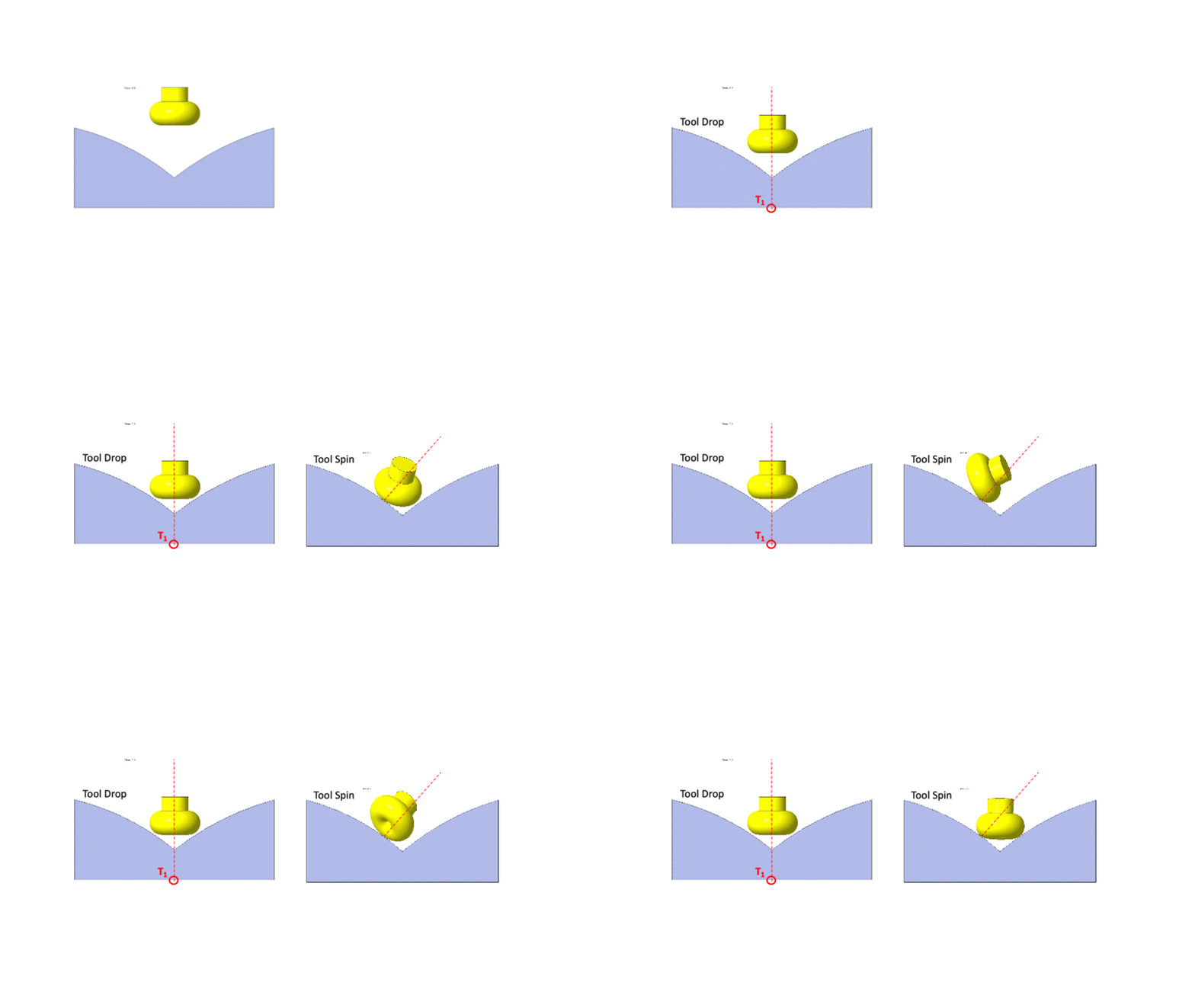
Drop Spin Tilt Methods the Concept: The tool drop onto the surface results in a single point of contact between the surface and the toroidal tool. At the point of contact a minor circle, referred to as the pseudo-insert, of the torus touches the surface. In previous methods, such as DTM, we have exploited the fact that if the torus is rotated about the axis of the minor circle, the pseudo insert retains contact with the surface. However, rotation of the tool about the surface normal also has the same property. Rotation of tool about the surface retains contact with the surface. This rotation alone does not lead to bringing the tool closer to the surface and has not been used in tool positioning before. However, in combination with the Drop Tilt family of methods this concept offers new posibbilities.

The tool drop onto a surface is shown in the figure on the left. The figure on the right shows the tool rotating about the surface normal.
-
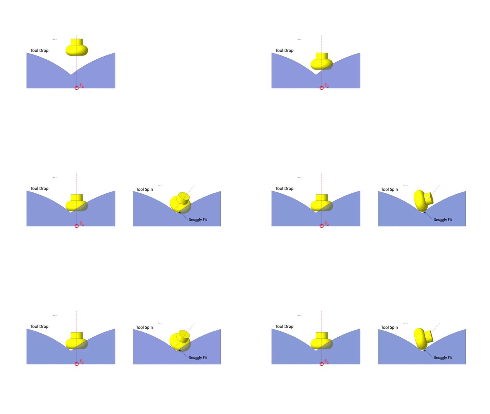
Drop Spin Tilt method for Machining Surface Intersections: The spin concept presented above was used to machine the surface at the intersection of two surfaces. In the figture above the tool drop on the intersection of two surface patches. The tool stradles the two surfaces, leaving a lot of unmachined material below it. The unmachined material depends on the orientation of the tool. The spin concept can be used to optimize the orientation of the tool at the point of crossing.
The surface of a toroidal tool has a large variation in the minimum principle curvature. The maximum curvature, however, remains constant. The figure below shows the tool being dropped onto the intersection between two surfaces such that the maximum curvature part of the tool is close to the interstion. The tool in this orientation gouges the surface. The spin is then used to eliminate the gouging and to ensure that the tool touches the intersecting surfaces close to the maximum curvature minimizing the material below the tool.
Positioning tool at surface surface intersection using the spin concept.
-
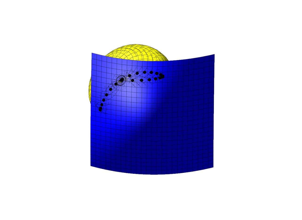
Drop Spin Method for Tesnsor Product Surfaces: The spin concept can also be used in conjunction with DTM. In DTM the tool is dropped along the vertical axis. It is also possible to drop the tool along other direction. When a tool is dropped along another direction the tool position that is generted is different. One can find a direction, such that the dropped tool touches the same point as the vertical drop. Even in this case the tilt results in a different second point of contact. This observation is shown in figure below. Many directions that lead to the same first contact point are found and the Multi-Point tool positions are determined for all of them. The figure shows the surface as seen from the bottom. The entire surface is visible. The tools are slightly visible confirming that the tools are just touching the surface. The tools are also visible beyond the surface boundary. The tool positions are plotted in the figure and the second point of contact is marked with a polyhedral. All the tool positions are valid and do not undercut the surface. All the tool positions have the same first contact point. The second contact point is spread around the first point. The multiple solutions around a point will be used in the future to determine a multi-point tool positionthat gives uniformly spaced contact points for the entire pass.

Virtual Machinist - A concept for autonomous machining
