-
The two beams from the stretcher are combined by the use of a 50% bream splitter, transmitted through a Faraday isolater and injected into a regenerative amplifier.
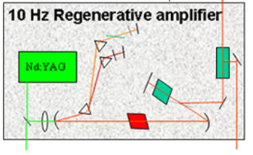
- The amplifier is an X-folder cavity having two focusing mirrors with 0.5 and 1 meter radii of curvature separated by 80cm.
- A Packels cell and a broadband polarizer are placed in one arm of the resonater, and prisms are placed in the other arm for spectral tuning.
- The gain spectrum of the amplifer must mathc the oscillator spectrum.
- Since the gain will be different for the two wavelengths, the two pulses must reach saturation at different times. The round-trip gain must therefore be equal in the two spectral regions.
- A set of three prisms are used to separate the two wavelengths. A slit is placed between the back mirror and the prisms to match the regenerative-amplifier gain spectrum to the long-wavelength spectrum of the oscillator.
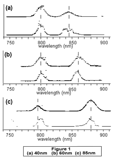
- A quarter-wave plate and broadband polarizers are placed in the short-wavelength arm to rotate the polarization and create a variable loss for the high-gain region of the spectrum.
- Lastly, we set the number of round trips to maximize the energy of the long-wavelength pulse (the energy ratio of the two pulses can be varied simply by rotation of the quarter-wave plate).
- The amplified spectrum (Figure 1) mathces the oscillator spectrum and the bottom trace is a single-shot spectrum of the amplified pulses.
- The energy of the system is determined by the gain at the longer wavelength.