The Emerging Radio Systems Group operates its own laboratory in room 4021 of the Engineering 5 building at the University of Waterloo, and shares equipment with other groups in the Department of Electrical and Computer Engineering. The lab covers signal generation, signal and network analysis, on-wafer and load-pull characterization and over-the-air measurement, from FR1 through the V, W and D bands.
Equipment
The instruments below can be booked by researchers outside the group. Rates are available on request and depend on whether the work is academic at the University of Waterloo, academic elsewhere, incubator or start-up, or industrial. Staff fees for setup, training and measurement are charged on top of the equipment booking.
Signal Generation
| Equipment | Capabilities |
|---|---|
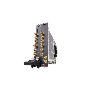 Keysight M5300A AWG | PXIe RF arbitrary waveform generator; 4 channels, 14-bit, up to 2 GHz instantaneous bandwidth, up to 16 GHz RF output. Direct generation of wideband modulated stimuli. Optional multi-channel (16×) for MIMO waveform playback. |
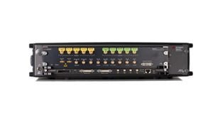 Keysight M8190A AWG | High-performance AXIe AWG; 2 channels, 14-bit (12-bit at maximum rate), 5 GHz analog bandwidth. Precision wideband waveform synthesis. |
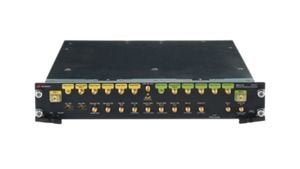 Keysight M8121A AWG | AXIe AWG module; 2 channels, 12/14-bit, up to 6 GHz, ODI stream-able. Multi-channel synchronized waveform generation for array excitation and coherent multi-port stimulus. |
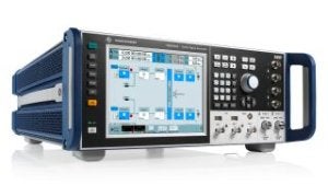 Rohde & Schwarz SMW200A VSG | Vector signal generator to 67 GHz; 16-bit baseband, 2 GHz wide modulation bandwidth. |
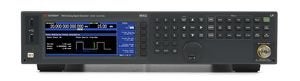 Keysight N5183B MXG | Analog microwave signal generator to 40 GHz. Low-phase-noise LO and CW stimulus for converters, mixers, receiver testing and interference injection. |
Signal Analysis and Network Analysis
| Equipment | Capabilities |
|---|---|
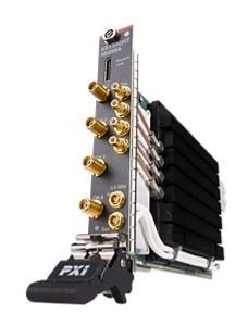 Keysight M5200A Digitizer | PXIe digitizer; 4 channels, 12-bit, 2 GHz bandwidth. Wideband IF capture. Option: multi-channel (16×) for coherent MIMO receive. |
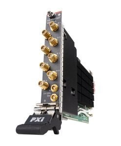 Keysight M5200A Digitizer + M5201A Downconverter M5200A + M5201A | Digitizer paired with a downconverter front end extending capture to microwave carriers (up to 16 GHz). Coherent wideband acquisition of modulated signals for EVM/ACPR and behavioural-model extraction. Option: multi-channel (16×) for coherent MIMO receive. |
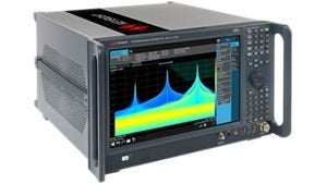 Keysight N9040B UXA Signal Analyzer | Premium signal analyzer to 50 GHz; up to 16-bit digitization with 1 GHz analysis bandwidth. Spectrum, EVM, ACPR. |
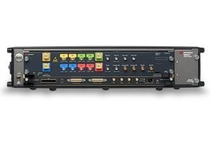 Keysight M8131A Digitizer | AXIe digitizer; 10-bit, 6 GHz bandwidth, 16 GSa/s, ODI stream-able. Ultra-wideband single-shot and streaming capture. |
| Keysight DSOS404A Oscilloscope | Infiniium S-Series oscilloscope; 4 GHz, 10-bit ADC. Time-domain characterization, multi-channel alignment, trigger and timing debug, and envelope/transient analysis. |
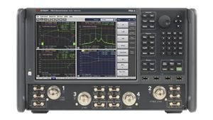 Keysight N5247B PNA-X Network Analyzer | Vector network analyzer to 67 GHz with nonlinear measurement suite. S-parameters, spectrum analysis, gain compression, IMD, and source- and load-pull-oriented characterization of transistors and power amplifiers. |
Other Equipment
| Equipment | Capabilities |
|---|---|
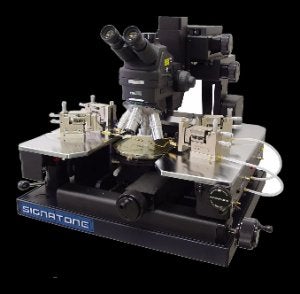 Signatone Probe Station CM-210 | High-precision analytical probe station with an integrated vibration-isolation table for on-wafer DC, CV/IV and RF characterization of 150–300 mm wafers. Supports RF probing up to 110 GHz with sub-micron positioning accuracy. |
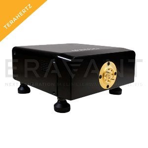 Eravant D-Band Upconverter STV-00-06-S1 | D-band waveguide upconverter translating DC–30 GHz IF signals to 110–170 GHz RF with 15 dB typical conversion loss, 20 dB harmonic suppression, and operation from a 9.16–14.17 GHz LO. |
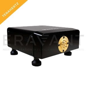 Eravant D-Band Downconverter STC-20-06-S1 | D-band waveguide downconverter converting 110–170 GHz RF signals to a 10 MHz–1.6 GHz IF with 20 dB conversion gain, 20 dBc harmonic suppression and −10 dBm input P1dB. Operates with a 9.167–14.167 GHz LO. |
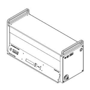 Focus Microwaves Programmable Tuner MPT-1818 | Programmable impedance tuner covering 1.8–18 GHz with independent tuning of the fundamental, second and third harmonics using three wideband probes. Supports harmonic load-pull and high-VSWR prematching (up to 80:1). |
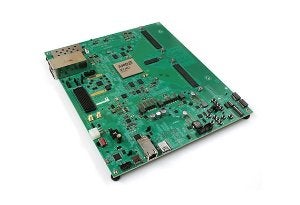 Xilinx RFSoC FPGA Gen 3 ZCU216 | Zynq UltraScale+ RFSoC Gen3 development platform: 16 × 14-bit 2.5 GSPS RF ADCs, 16 × 14-bit 9.85 GSPS RF DACs with integrated DDC/DUC, quad-core Arm Cortex-A53, dual-core Cortex-R5F, 4,272 DSP slices and 930k logic cells. |
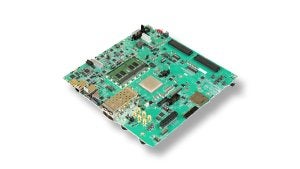 Xilinx MPSoC FPGA ZCU102 | Zynq UltraScale+ MPSoC development platform: quad-core Arm Cortex-A53, dual-core Cortex-R5F, 2,520 DSP slices, 599k logic cells, 24 × 16.3 Gb/s GTH transceivers and dual FMC HPC connectors. |
| Amplifier Research Driver Amplifier 5S1G4M3 | Broadband tunable-gain RF driver amplifier covering 0.8–4.2 GHz with 7 W output at 1 dB compression, 37 dB maximum gain, 10 dB gain adjustment and ±2 dB gain flatness. |
| Amplifier Research Driver Amplifier 40S1G4 | Broadband tunable-gain RF driver amplifier covering 0.7–4.2 GHz with 44 W output at 1 dB compression, 46 dB maximum gain, 10 dB gain adjustment and ±2 dB gain flatness. |
Booking and Terms
- Requests require at least 72 hours’ notice and are processed by Dr. Slim Boumaiza. The minimum booking is a half day.
- Charges cover the booked period, including any unused portion.
- A discount applies based on frequency of use per invoicing period. Subscriptions to the facility by the term or by the year are also available.
- Users are expected to bring their own cables.
To enquire about access, rates or a subscription, please use the contact page.
Product photographs are the property of their respective manufacturers and are shown to identify the instruments in the laboratory.