Last updated October 2024
Telecommunications Room Provisioning
Dimensions and Location
- Multi-story buildings SHOULD have a minimum of one Telecommunications Room per floor
- or otherwise provide a Telecommunication Room of sufficient capacity and dimensions and be within cabling distance requirements to serve adjacent floors
- Telecommunications rooms should be located as close as possible to the centre of, and on the same floor as the area it is intended to serve and so that cable length does not exceed 90 m or 295 feet.
- Telecommunication rooms in multi-floor buildings should be vertically aligned
- Standard telecom room dimensions are provided below.
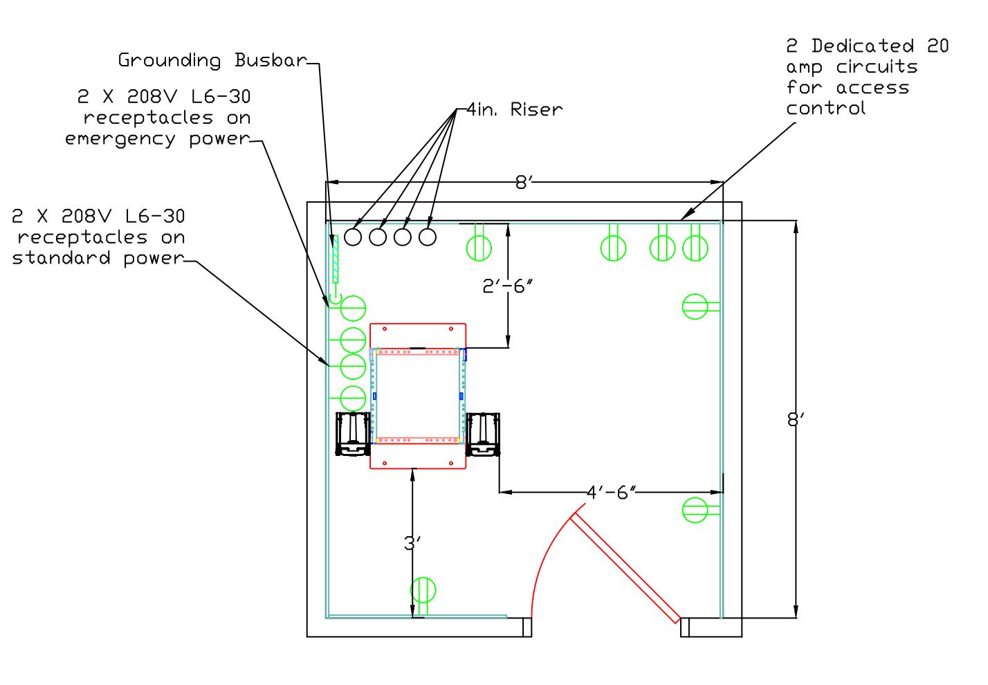
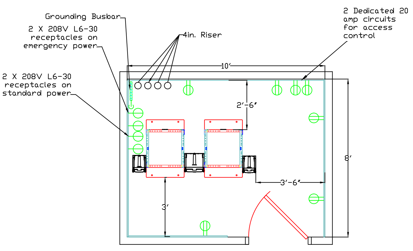
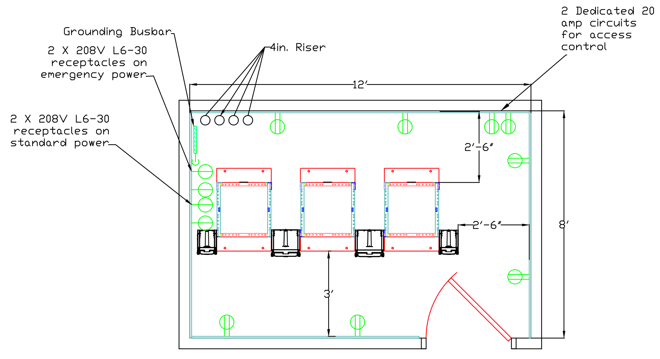
- At a minimum the room dimensions must provide the following clearances: 0.75 m (2.5 ft) in front of, behind and on one side of the network rack row
- (see figures 1,2,3 below for required room layout).
- Any door must not open into clearance space on any side of the rack.
- no equipment can be mounted in any of the clearance space.
Minimum Telecommunication Room Dimensions
|
No. of drops per serving area |
Minimum TR dimensions |
|---|---|
|
0 – 384 |
8’ x 8’ |
|
385-768 |
10’ x 8’ |
|
769+ |
12’ x 8’ |
- These are minimum sizes and may need to be increased if the TR will be hosting IT equipment in addition to network switches
- University of Waterloo IST networks team must be consulted for any variation
Room Characteristics
- Walls should be covered with 20 mm (3/4in.) plywood, 8ft high. Plywood should be fire rated or covered with 2 coats of fire-retardant paint. (as per local code)
- Treat floors, walls, and ceiling to minimize dust
- Minimum ceiling height should 3 m (10 ft)
- Suspended ceilings are not permitted in telecommunications spaces
- Doors should be at least 0.91 m (3 ft) wide and 2 m (6.6 ft) high
- Conduit should be installed for access control
- Effort should be made to prevent sound leakage from the room
- At a minimum weather stripping should be installed on all doors exiting the room
- Walls should contain soundproofing insulation
- Equipment that is not related to the support of telecommunications rooms (piping, ducts etc) should not be in, or pass through telecommunications rooms
Permitted room services
- IST managed services such as
- Networking
- Electronic access control
- Alarm systems
- Audio Visual systems
- Telephone systems
Power
- Convenience receptacles (duplex 15A 110V) located every 1.8 m (6 ft) around perimeter walls
- Two (2) 30A 208V on separate circuits, for equipment power, with L6-30 connectors on emergency power. (see figure 1,2,3 for location)
- Height should be no higher than the middle of the network rack
- Two (2) 30A 208V on separate circuits, for equipment power, with L6-30 connectors on standard power. (see figure 1,2,3 for location)
- Height should be no higher than the middle of the network rack
- A grounding and bonding system, tying together all of the telecommunication rooms to the building ground must be installed. See TIA-607 Commercial Building Grounding and Bonding Requirements for Telecommunications.
- Two (2) dedicated 20A circuits, not hooked up to emergency power, terminated in a junction box for future access control. Circuits should be located on the bottom right-hand corner of the wall mounted plywood on the wall opposite the door.
- Each telecommunication room is to be provided with its own dedicated panel. Panel size is dependent on room capacity and should be sized with future growth in mind.
- Each telecommunication room panel is to be fed from a dedicated distribution panel in the main electrical room. This panel is to have its own transfer switch for emergency power or be provided with an exterior connection for a backup generator.
- If specified in the building plan, a UPS unit is to be installed ahead of the main telecommunication room distribution panel to prevent service interruption on power failure and maintain phones during emergencies.
Lighting
- Lighting should be a minimum of 500 lux at 1 m AFF
- Lighting layout should be coordinated with equipment layout (see figure 1,2,3 below)
- Emergency lighting to be provided
HVAC
- Temperature range should be 18 ⁰C to 24 ⁰C (64 ⁰F to 75 ⁰F)
- Humidity range should 30% to 55% relative humidity
- All telecommunication rooms to be supplied temperature and humidity control from one independent split unit.
Trays, Sleeves, and Ducts
- Cable tray from hallways should extend into the telecommunications room and connect to a cable tray extending across the top of the equipment racks
- The telecommunication room riser system consists of two (2) 100mm (4in.) conduits or sleeves. The sleeves with bushings should extend 25 to 76 mm (1 to 3 in.)
- All trays and sleeves should be fire rated as required.
Telecommunication Room Layouts
Figure 1: 8ft. x 8ft. Telecommunications Room

Figure 2: 8ft. x 10ft. Telecommunications Room

Figure 3: 8ft. x 12ft. Telecommunications Room
