Introduction
Up until now, we’ve focused mostly on outputs. Now we’re going to go to the other end of spectrum and play around with inputs. In experiment 2, we used an analog input to read the potentiometer. In this circuit, we’ll be reading in one of the most common and simple inputs – a push button – by using a digital input. The way a push button works with your Arduino Uno R3 is that when the button is pushed, the voltage goes LOW. Your Arduino Uno R3 reads this and reacts accordingly.
In this circuit, you will also use a pull-up resistor, which keeps the voltage HIGH when you’re not pressing the button.
Parts Needed
You will need the following parts:
- 1x Breadboard
- 1x Arduino Uno
- 1x LED
- 1x 330Ω Resistor
- 7x Jumper Wires
- 2x Push Buttons
- 2x 10k Resistors
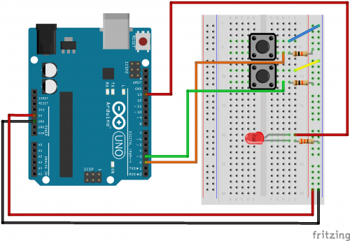
Hardware Hook-up
Ready to start hooking everything up? Check out the Fritzing diagram to see how everything is connected.
Open the Sketch
Open up the online Arduino IDE on 123D circuits on your computer and laptop. Coding in the Arduino language will control your circuit. Copy and paste the following code into the 123D circuits code editor and follow along. Hit upload, and see what happens! Make sure to spend time adjusting the code here.