IQC postdoctoral fellow Katanya Kuntz led the discovery of a new technique for measuring the length of an optical cavity, without any initial calibration.
An optical cavity is an arrangement of mirrors that allow a beam of light to circulate around a closed path. Cavities can be used to calibrate a laser’s frequency, perform precise length measurements, generate non-classical light and produce groups of interlinked or entangled photons, called cluster states, that are useful for performing complex quantum computing tasks. However, knowing the cavity’s free spectral range (FSR), which is related to path length, is needed before the cavity can be used. Until now, existing techniques for determining a cavity’s FSR relied on a calibrated fast receiver, or specialized lasers, which are not readily accessible.
The new technique does not require any specialized equipment, or for the measurement components to be calibrated beforehand. “It’s a very robust, simple and user-friendly method that uses available technology,” said Kuntz.
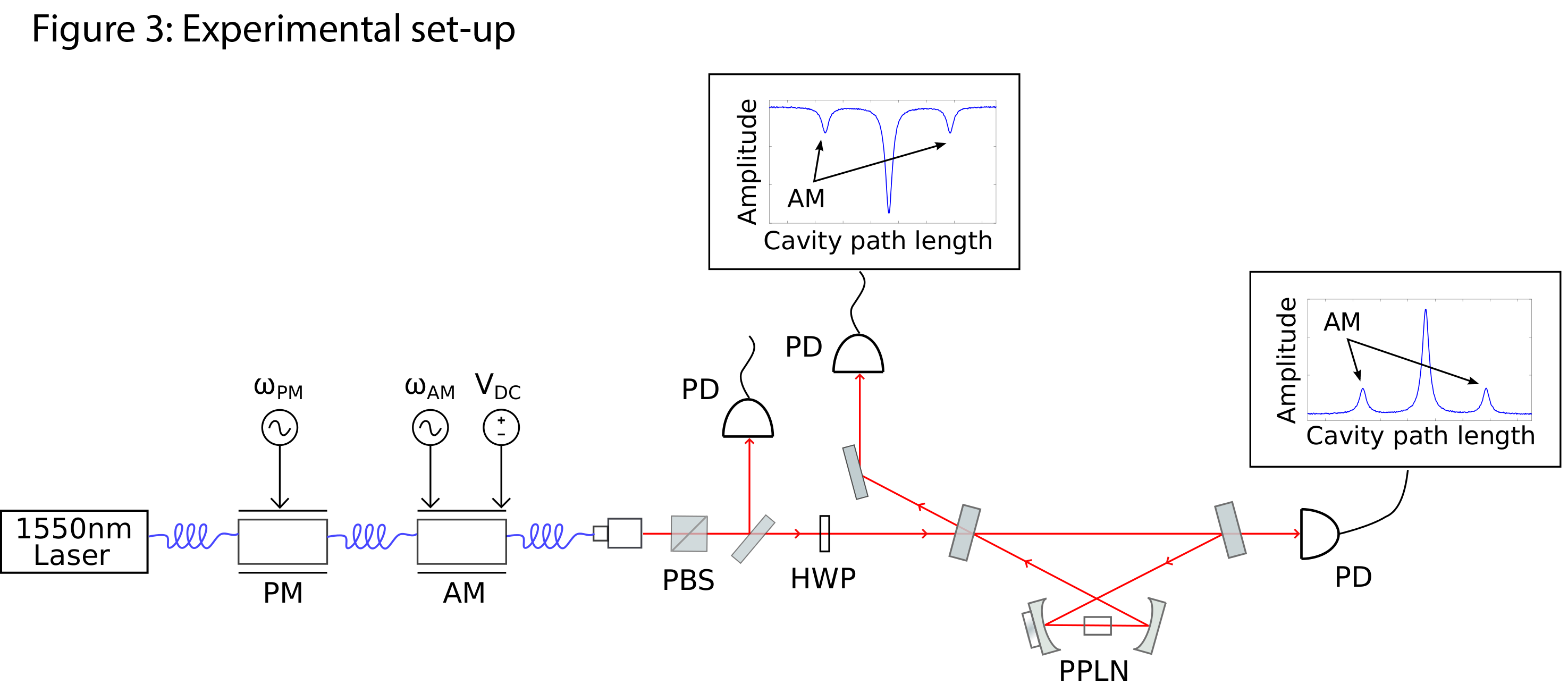
Figure 3: Experimental set-up for measuring the length of an optical cavity
Kuntz first sent the laser or light source through a phase modulator, followed by an amplitude modulator that redistributed the laser’s energy. The phase modulation secured the mirror positions on the optics table so the laser would circulate inside the cavity. The amplitude modulator took some of the laser beam and shifted its frequency. One way to imagine how an amplitude modulator works is to think of the keys on a piano. Before the modulator, the laser was just one note (middle ‘c’). After the modulator, the laser has three notes: one below (‘b’) and one above (‘c#’), as well as middle ‘c’. The above and below notes around the center note are called sidebands. Changing the modulation frequency changes the sideband frequency. For example, the above and below notes become ‘d#’ and ‘a’, while middle ‘c’ stays the same.
The light then travelled through the optical cavity, measured by the photo detector at the end. The detector reported maximum light intensity when the laser and sidebands matched the frequency of the light within the cavity. That is, when all three piano notes were spaced one octave apart, where an octave is analogous to an FSR. Less light was measured as the frequency changed and the sidebands stopped circulating in the cavity (i.e., were not one octave apart).
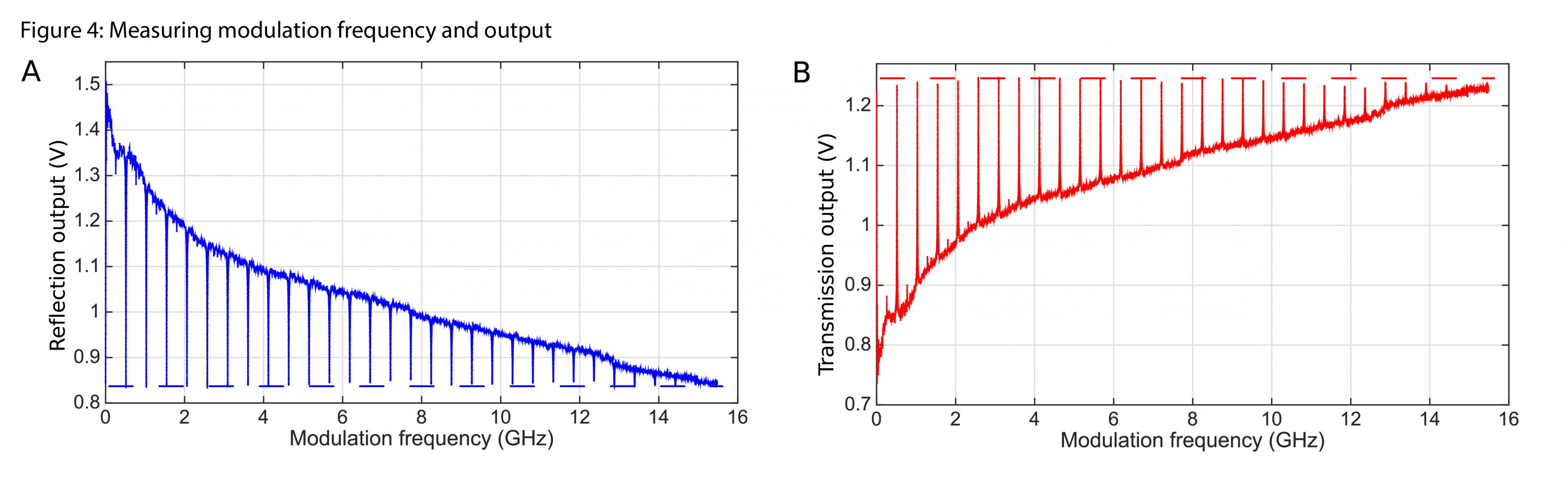
Figure 4: Measuring modulation frequency and output
“We found that measuring the spacing between the peaks revealed the FSR of the cavity,” explained Kuntz. “Any researcher who needs a fast and simple way to find a cavity’s FSR can use this.”
With potential applications for both classical and quantum research, the measurement technique could also be useful in the telecommunications industry for calibrating lasers to transmission channels.
This research was conducted at the University of New South Wales, Australia with international collaborators while Kuntz was earning her PhD. The results are published in the paper Ultra-wide frequency response measurement of an optical system with a DC photo-detector, appearing in Optics Express January 23.