Design team members: Adam Bruecker, Winnie Leung
Supervisors: Prof G. Heppler, Christian Anhalt
Background
Composite materials for aeroplane construction
Composite materials have proven to have very high strength-to-weight and stiffness-to-weight ratios, which is a very desirable property for aircraft design and construction. Due to the remarkable specific properties of composite materials, component weight savings of up to 30% have been achieved. This technology has been progressing in the aircraft construction industry as more and more parts of the aircraft are made from composite materials.
The use of composite materials in aircraft construction offers other possibilities, given that composite materials, unlike metallic materials, have different properties in different directions. For instance, depending on the fibre alignment, the material may be stronger or stiffer in a certain direction. A section of material could also be induced to twist in a certain direction, if forces are applied in the appropriate fashion to the material e.g. coupled extensive trussing. In fact, such exists for all materials, however the ability to influence material properties of composite materials by modifying their construction allows us to tailor their behaviour in a desired, predefined manor. (See Figure 1)
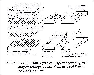
Figure 1 : Composite material construction
Improving flight efficiency through manipulation of aerodynamic loadings
The wings of modern long-range aircraft are characterized by a large wing span and a high aspect ratio. The slimness has the disadvantage of large deformations in bend and torsion, if they are not rigidly built. In addition, the „wash out“ phenomenon occurs as a result of the sweep of the wing which makes the arircraft difficult to control at high velocities. Since the wings of aircraft are currently only passive structures, increases in aerodynamic efficiency can only be achieved by changing the velocity or weight of the aircraft.
With the ability to actively manipulate the coupling between the wing exterior torsion and the angle of incidence, an optimal deformation suited for different phrases of flights can be achieved. An active system can potentially be implemented directly in the load path of the outer part of the wing, thus providing the capability of active deformation, at any time, to achieve an optimal wing configuration.
Due to the large forces required to deform the wings and the rigidity of the wing, it is assumed that this deformation will not be achieved using Piezo-ceramics or SMA wire, but from conventional hydraulics actuators. By a direct twisting of the outer wing, the lift of the wing is shifted, concentrating the force more towards the fuselage. This reduces the bending moment at the point where the wing and fuselage are connected, which substantially decreases chances for the material fatigue in this area.
A large part of the design process will be the determination of the prescribed aerodynamics loadings to design the structural deformation of that structure. Here, the reaction of the wing deformation to the aerodynamic loadings will be examined, as well as the resulting structural deformations. It is hoped that significant improvements can be reached with respect to lift, resistance reduction and weight, which will lead to a more environmental, safer and more economic flight.
Project description - adaptive twisting of wing
This project aims to look at deformation of the outer part of an aeroplane wing, and how this deformation can be used to improve the flight characteristics of the aeroplane. More specifically, the integration a deforming wing tip system into a transsonic aeroplane to optimize the flow, load, and structure control during the phases of flight where lift is most required, with the respective flow and operating conditions taken into consideration. Objectives in examining the use of composite building material and the mechanics of the adaptive twist were set out in the design phase.
The purpose of this project is to integrate a system into a transsonic airplane to optimize the flow, load, and structure control during the phases of flight where lift is most required (takeoff/landing), with the respective flow and operating conditions.
In
summary,
it
is
hoped
that:
The
operating
cost
will
be
lowered,
as
well
as
a
reduction
in
fuel
consumption.
Due
to
controllable
structures
with
active
load
control
and
contour
adjustment,
planes
can
be
less
sensitive
to
high
frequency
turbulence,
as
well
as
improved
gust
load
reduction.
Problem statement
To achieve maximum overall aerodynamic efficiency of flight mechanics against aeroelastic conditions, the outer portions of aircraft wings, made out of laminated fibre reinforced material aligned in an optimal fashion, will be designed to have the ability to actively twist through active torsion mechanisms.
Design methodology
Objectives breakdown
Study the aeroelastic behaviour of a flat plate built out of laminated CFRP (Carbon Fibre Reinforced Plastic)
-
Determine the patterns between the fibre alignment of the material and the corresponding twist reactions.
-
Aeroelasticity: effects aerodynamic loadings on the flat plate model
Design the wing section (as a flat plate) built out of CFRP
-
Decide on proper construction (fibre alignment, material layering, configuration of ‘plates’) to achieve desired twisting motions.
Model evaluation: Approximation of the aerodynamic benefits of the resulting design
-
Determine if there is a reduction of the bending moments at the junctions between the fuselage and the wings
Devise a way to mechanically twist the wing.
-
How to apply forces to the composite construction? Hydraulics? Piezoelectric actuators?
-
Power supply system considerations
Design process (in accordance to above objectives)
1. Identifying needs (Reduction of Project Scope)
First approximation of the aerodynamic benefits of twisting the outer portion of the wing
Reduction
of
bending
moment
at
the
junction
between
the
fuselage
and
the
wings
Divide
project
focus
into
Flat
Plate
Modelling
of
CFRP
with
aerodynamic
considerations
(incompressible
subsonic
inviscid
flow)
Structural
design
of
Active
Torsion
Mechanics
for
the
outer
portion
of
the
wing
–
black
box
approach:
given
I/O,
without
details
of
model
within,
design
transfer
function
to
achieve
desired
I/O
relationship.
2.
Planning
and
specifications
(overall
goals,
constraints,
boundary
conditions)
Flat
plate
modelling
Develop
a
working
understanding
of
the
mechanics
of
laminated
fibre
reinforced
material
(properties,
characteristics
and
reactions
to
external
forces)
MATLAB
programming
to
simulate
material
behaviour
with
respect
to
loadings
(bending
coupling,
twist
coupling)
Active
Torsion
Mechanics
Technical
specifications:
target
twist
angle,
target
time
constant
and
displacement
3.
Concept
generation
Flat
plate
modelling
different
alignments
of
material
that
will
achieve
the
desired
twisting
motion
Active
torsion
mechanics
Investigate
means
of
applying
forces
on
the
structure
–
Hydraulic
actuators?
Electrical
Motors?
Placement
of
these
actuators/
motors
Power
and
bandwidth
requirement
(effective
operation
frequency
range)
4.
Concept
selection
Select
the
optimization
scheme
-
optimization
problem:
Genetic
Algorithm
–
solution
selection
Evaluation
matrix/
criteria
that
defines
‘desired
twisting
motion’
5.
Concept
testing
Presentation
of
the
concept
through
sketches
Mathematical
modelling
of
the
concept
Emulation/
simulation
of
concept’s
behaviour
under
specific
loadings
6.
Construction
and
testing
Physical
Construction
of
prototype
Testing
of
Prototype