Design team members: Chad Schmitke
Supervisor: John McPhee
Background
Walking robots have many potential applications in areas where uneven terrain prohibits wheeled vehicles from travelling. This advantage is often at the cost of a more complex control system due to the increased degrees of freedom. Hexplorer is an ambitious ongoing project to develop a small, autonomous walking robot. The project includes many facets of design, including mechanical design, motor control systems, walking gait algorithms, and sensory apparatus.
The Hexplorer walking robot project (initially termed "Hexotica") was started in 1996 by a group of Systems Design students under the guidance of Professor John McPhee. The aim of the project was to explore robot design and control through the creation of a small six-legged autonomous walking robot.
One of the most difficult aspects of the design has proved to be the construction of a reliable 3-degree of freedom leg. Most robots of this size only have legs with 2 degrees of freedom.
Project description
The goal of this workshop, is to design and build one fully functional, 3 degree of freedom, leg module. The leg module will receive as inputs an XYZ coordinate in space and a velocity vector. It will then perform the inverse kinematics and joint manipulation necessary to produce the desired leg motion. Sensory feedback from the leg will also signal the module's onboard processor when the leg has been blocked or has some fault has occurred.
By designing and building a reliable leg module, future groups will be able to test various gait and obstacle avoidance algorithms using a collection of these leg modules as the test bed.
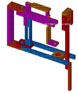
The fist phase of the project, the mechanical design of the leg, has been completed. The integration of the circuitry and onboard software is scheduled to be finished by March 28, 2000. A solid model of the mechanical design is shown on the right.
Design methodology
The methodology used in the first phase of the project was straightforward. It consisted of the following steps:
-
Idea generation - basic pencil and paper sketching
-
Idea selection - designs were compared based on a set of criteria
-
Proof of concept - chosen idea was simulated to ensure it met the criteria
-
Component design - Individual parts to make the design were developed
-
Machine-ability analysis - components were altered to ease machining
-
Final design verification - a solid model of assembled parts was created to verify the design before prototyping
For the second phase of the project, integrating the circuitry and control software, a more direct method will be used. An initial design will be developed for each, and then an iterative of approach will be used as flaws with the initial design are discovered.