Design Team Members: Daniel Fernandes
Supervisor: Professor Jan Huissoon
Background
Arc welding is one of several processes for joining metals. By applying intense heat, metal at the joint is melted. After the metal cools and solidifies, a metallurgical bond is created. MIG welding, (Metal Inert Gas welding) is a form of arc welding uses a continuous spool of metal wire, to perform the welding. The wire feeds out the end of the welding gun, and a welding arc is formed at the gun tip using electric current. During welding (see Figure 1), an inert gas is used to shield the surrounding air from the intense heat of the weld arc.
Figure 1 – Essential components of MIG welding
There are two main parameters that affect the results of MIG Welding. The first is the heat level, which directly determines the required voltage to create the welding arc. The second parameter is the speed at which the wire is fed out of the welding gun. Often one parameter will affect the other, so they need to be adjusted during the welding process.
Project description
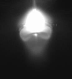
Figure 2 – Infrared spectrum image of weld pool being formed
The University of Waterloo’s Welding Laboratory contains a MIG Welding Robot that possesses two welding tips on the same robotic arm. During MIG Welding, each tip feeds a wire into the welding torch, and melts the wire, forming a hot liquid weld pool. This pool cools to form the weld bead, which consists of solid metal. Most of the visible features of the weld formation are clearer in the infrared spectrum, as seen in Figure 2, which represents one frame of the process. The dark regions surrounding the weld pool are the solid (colder) areas of the metal.
The purpose of this project is to provide numerical and visual measurement of the weld width, length and/or shape based on digital images of the welding process. The information obtained may eventually be used to control the welding process, or to suggest ways of improving welds, although this project will focus mainly on characterizing the features in the digital images.
Design methodology
Welding
equipment
The
setup
must
include
several
components,
many
of
which
are
already
available
in
the
welding
laboratory.
Specifically,
the
welding
robot
will
perform
the
weld
by
moving
its
robotic
arm
according
to
pre-programmed
instructions.
In
addition,
the
robotic
arm
must
be
fitted
with
a
MIG
welding
gun,
and
connected
to
the
wire-feeding
spool.
Capture
equipment
In
order
to
capture
images
of
the
welding
process,
the
robotic
arm
must
also
be
able
to
hold
the
camera
that
is
used
to
film
the
welding.
The
camera
must
be
retrofitted
with
an
infrared
filter.
Computer
hardware
In
order
to
store
the
images
received
from
the
video
camera,
a
computer
must
be
used
in
conjunction
with
a
“framegrabber
card”,
which
takes
a
video
input
and
converts
it
to
a
series
of
still
images.
These
images
must
be
stored
on
the
hard
drive
of
the
computer
in
order
to
be
processed
at
a
later
time.
They
could
potentially
be
processed
in
real-time.
Figure 3 – project phases
Software
The
software’s
user-interface
is
to
be
written
in
Visual
C++.
The
mathematical
manipulation
and
feature
detecting
portion
will
be
performed
mainly
in
MATLAB,
and
will
use
various
techniques
to
process
the
image
in
two
stages:
pre-processing
and
feature
extraction.
Pre-processing
The
pre-processing
stage
will
make
the
image
clearer
and
easier
to
quantify.
This
may
involve
some
noise
removal,
in
order
to
‘clean
up’
the
picture
and
avoid
false
detections.
In
addition,
techniques
such
as
thresholding
and
edge-detection
will
be
used
to
reveal
important
features
in
the
image.
Feature
extraction
Using
pattern
recognition
techniques,
the
locations
of
features
of
the
weld
image
will
be
mathematically
computed
and
stored.
Specific
measurements
would
include
a
measure
of
the
orientation,
width
and
length
of
the
weld
relative
to
the
camera’s
frame
of
reference.
In
addition,
it
may
be
possible
to
fit
a
curve
to
the
boundary
of
the
weld
pool.